The challenge
For my master's thesis at the Technical University of Munich, I worked on a mobile hydraulic lower-limb exoskeleton. The longer-term motivation was assistance for people with paraplegia during movements such as standing, sitting and walking with crutches. My thesis goal was narrower and testable: turn an earlier concept into a functional, position-controlled prototype, then investigate how accurately it moves and how efficiently its hydraulic drive converts electrical power into motion. The project was carried out in collaboration with an industrial partner specializing in hydraulic systems. This was a laboratory demonstrator, not a clinically validated walking aid.
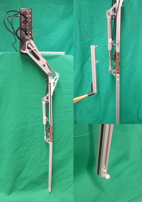
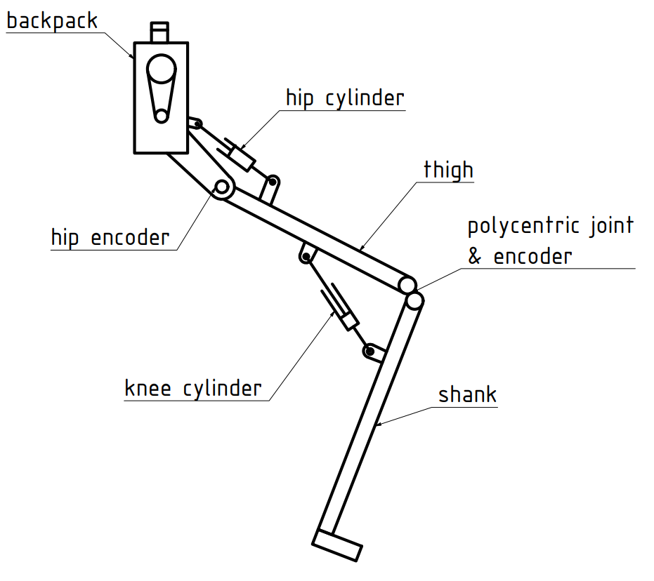
I examined and dismantled the previous prototype, revised the mechanical design, integrated more capable hydraulic cylinders and rebuilt the right-sided leg together with its backpack-mounted power and electronics. The leg has three sagittal-plane degrees of freedom: hydraulically driven hip and knee joints plus a passive ankle. The experimental setup shown above (Figure 3.1 of my thesis) documents the actual built hardware.
Mechanical and hydraulic redesign
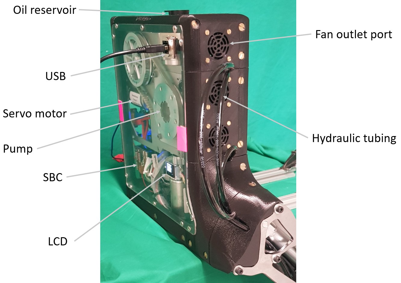
I used CAD and finite-element analysis to assess the structural parts and cylinder mounting geometry under load. Aluminum profiles and brackets made the frame adjustable for development, while selected 5 mm stainless-steel components were shaped using topology optimization. The optimized steel parts saved 0.517 kg (26.58%) while retaining an acceptable simulated safety factor. I replaced the earlier low-power cylinders with 3 kN hydraulic cylinders and integrated the power unit into the backpack. Keeping mass off the lower leg mattered because distal weight works against comfortable motion.
Trajectory generation and control
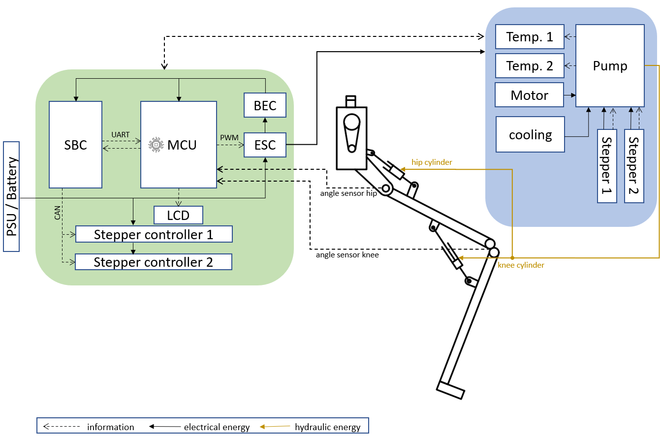
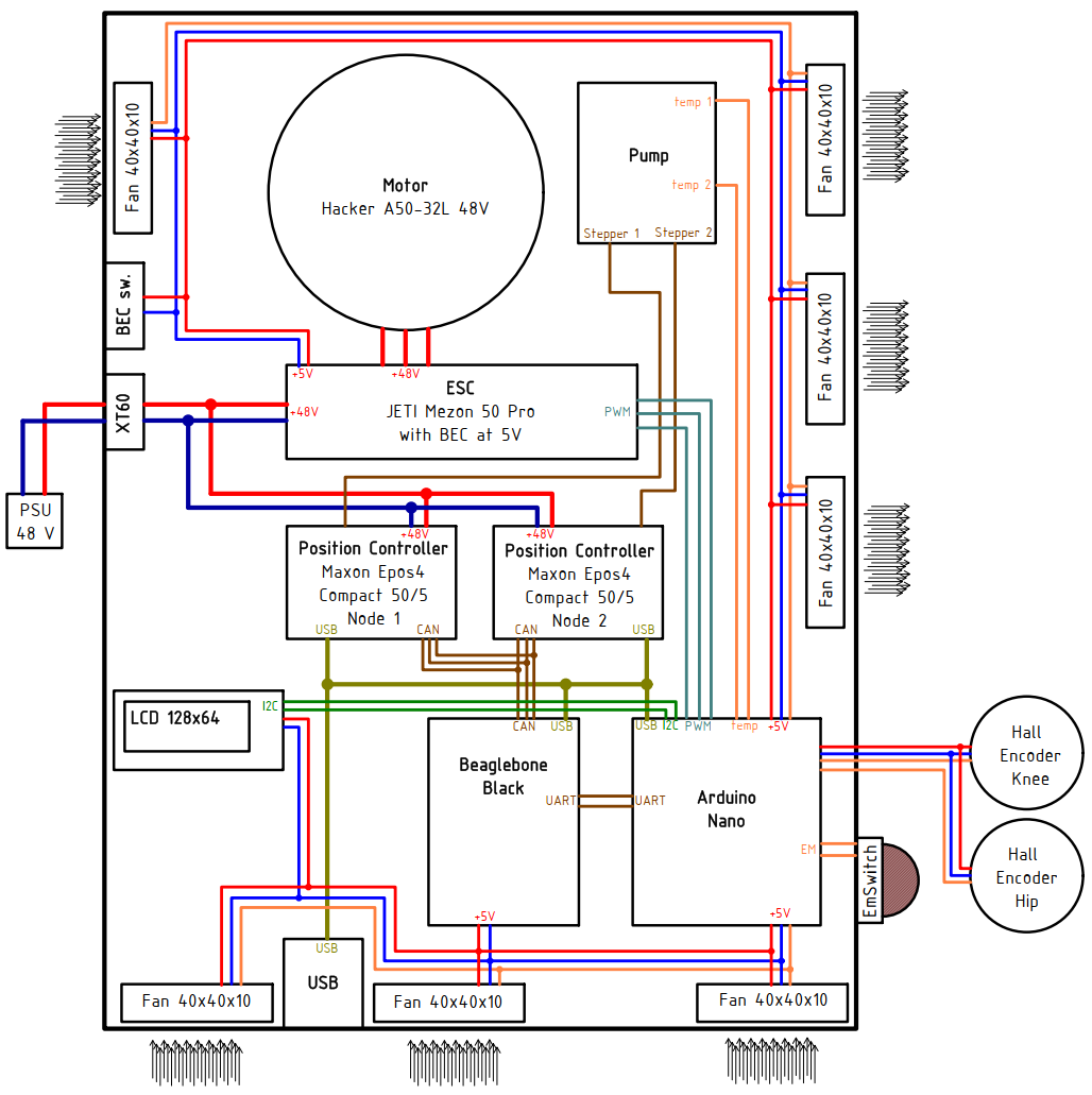
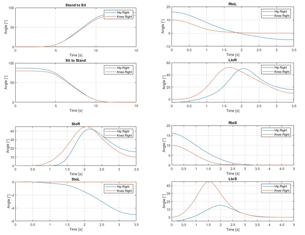
The intended motions were defined as hip and knee angle trajectories for standing, sitting and steps. I translated joint targets into hydraulic-cylinder positions through a kinematic model. The low-level motion controllers use position control with velocity-based pre-control so each cylinder can follow its commanded trajectory. The device architecture connects a single-board computer and microcontroller over UART, and controls the EPOS4 motion modules over CAN. The backpack houses the electronics, hydraulic drive and interface rather than placing all of that hardware on the moving limb.
Testing the prototype
I ran two types of experimental evaluation. First, I tracked the foot and leg while executing predefined motions, including tests with external load. A Polaris-Vicra optical tracking system measured the end-effector position independently of the joint sensors. Its specified 0.25 mm volumetric accuracy is a property of the measurement system, not the exoskeleton's achieved precision. I compared the observed foot path, position error and thigh/shank angles with the intended motion.

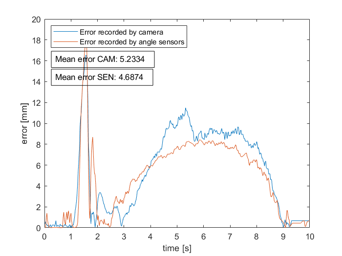
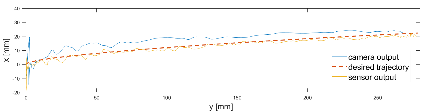
External forces caused substantial positioning errors and exposed structural deformation, especially in the adjustable aluminum-profile sections. The absence of check valves also meant the cylinders could not hold position without continued pumping. These results were valuable precisely because they identified limits that a controller-only simulation would miss.
Hydraulic efficiency and lessons learned
For the second experiment, I compared mechanical output power with the electrical power delivered to the hydraulic drive across several loads and motor speeds from 1,000 to 4,000 rpm. The measured efficiency generally improved with higher loads and lower motor speeds, although too little speed prevented the actuator from lifting a load. The plot reports system efficiency for those tested conditions, not a claim about every hydraulic exoskeleton.
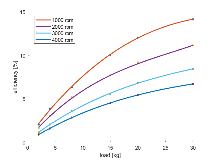
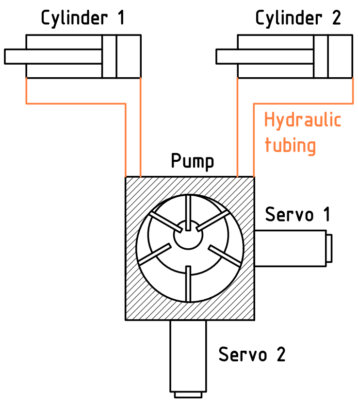
The final prototype established a physical test platform and a position-control baseline. Its limits were equally instructive: the two pumps share a mechanically coupled shaft, so the joints are not perfectly independent; the hydraulic unit supports only two actuators; the hoses and cylinders were not originally designed for exoskeleton kinematics; and simple position control cannot cancel strong load-induced deformation. Addressing those mechanical and hydraulic constraints would be essential before considering more advanced assistance or deployment.